(2014-02-26)
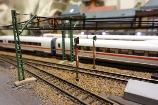
Zゲージ用の信号機を自作しました。
ポイントの切り替え方向のみを示す簡単なものです。
夜景での運転が増えたため、ポイントの切り替え方向がすぐに分かるようにしました。
また、電球色中心の夜景に、赤や緑の光が加わりました。
I made luminous signals for Spur Z layout.
The signal indicates turnout direction.
Since I prefer night view drive, It was important to recognize the turnout direction. I made it possible by this luminous signals.
Furthermore, it added green and red illumination to my night view.
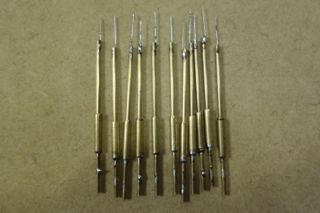
支柱はφ1.0mm、台座部分はφ2.0mmの真鍮パイプです。
LEDの固定部には、φ0.2mmの燐青銅線を使っています。
Main mast : φ1.0mm / Basement : φ2.0mm Brass pipes
LED support : φ0.2mm phosphor bronze wire.
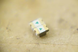
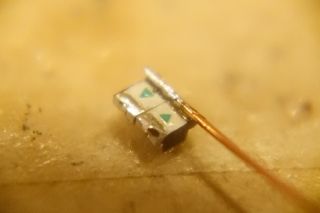
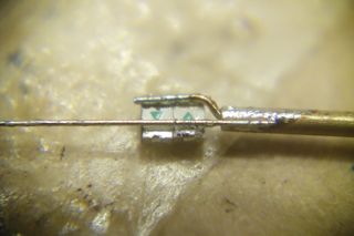
LED部分は、2.0mmx1.25mmのLED2個を逆極性に並列接続します。
両面テープの上に並べてハンダ付けし、中心線はUEW φ0.32mmを使っています。
また、光が混ざらないよう、接触面は事前にポスカで黒く塗っています。
2 LEDs soldered in reverse polarity each other.
UEW φ0.32mm is using for common cable.
For this soldering, temporary, I held them by adhesive tape.
And also, I painted each LED’s side in black, for optical isolation.
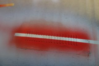
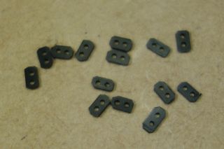
遮光板を作ります。
電子部品の静電気防止トレイが、黒くて遮光性に優れていたのでこれを利用して作りました。
φ0.7mmの穴を約1.25mm間隔で開けています。
Made a shade plate.
For this parts, I use anti-static tray of surface mount devices.
It colored black and good for shading.
I cutted it and drilled φ0.7mm holes at 1.25mm spacing.
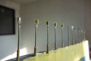
遮光板を低白化タイプの瞬間接着剤で固定し、塗装します。
遮光板部分はマスキングし、全体を黒のサフェーサーで塗装後、着色します。
Adhere the shade plate by low white residue grade cyanoacrylate adhesive.
Mask the shade plate and paint it by black surfacer. After that, paint it by lacker.
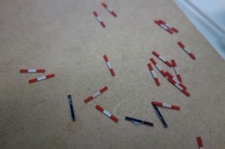
補助標識を作ります。
エバーグリーンの1×0.2mmのプラ板を使用しています。
Made auxiliary sign board.
I use Evergreen’s 1×0.2mm Plastic plate.
信号機本体は完成
この形状は、ハンガリー国鉄方式に準拠します。
下記HPを参考に致しました。
Finish
This shape has compliant to the Hungarian national railways(Máv) style.
I referred to the following website.
Thank you to the “European Railway Signalling Server”.
http://www.carreweb.fr/european-railway-signalling-server/signalling_en.html
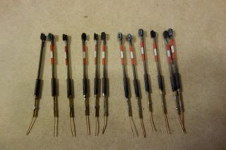
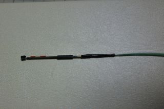
配線をします。
ラッピングワイヤをUEWと柱にそれぞれハンダ付けし、
熱収縮チューブで保護します。
Wiring
Solder the wrapping wires to the UEW and the pipe.
Covered them with shrink tube.
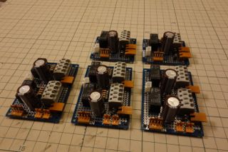
回路
リレーとコンデンサーを使い、
ポイントの切り替えと、信号機への電流反転回路を作りました。
コンデンサは2200uFです。
Circuit
I use relays and capacitors(2200uF) to control turnouts and for inverting the current for luminous signals.
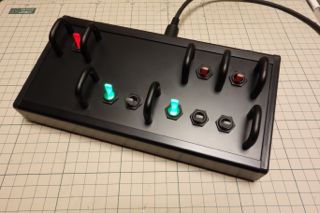
制御盤
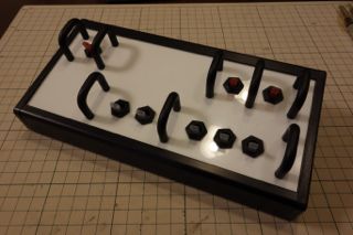
タカチケースのCF 22-11と、日本開閉機のTL-22トグルスイッチを使用しました。制御盤からは制御回路のリレーをON-OFFするだけなので、
ポイントと信号機を制御しても、ポイント1カ所あたりの配線は1本(+共通 GND)だけですみます。
また、スイッチのサイドにはガードが付けてあり、スイッチの保護と手探り操作の補助をしています。
Control Box
I choosed “CF 22-11” (by Takachi electric company) and “TL-22” luminous toggle switches (by NKK).
This box simply turn on/off the relay. It requires just 1 wire per 1 turnout even if you control turnouts and 2~3signals.
And also, I installed switch guards for protecting switches and helping blind operation.
制御盤試作
アルミ加工前に、プラ板で試作をし、バランスと操作性を確認。
Prototype for Control Box
Before metal plate processing, I made prototype by plastic plate for checking spacing and controllability.
